3D Gaussian Splatting, Matterport or LiDAR Point Cloud? The Complete Scanning Technology Selection Guide for Hong Kong Facility Managers
3D Gaussian Splatting (3DGS), Matterport, and LiDAR point cloud are three scanning technologies with fundamentally different principles and strengths: 3DGS prioritises visual fidelity and immersive “walkthrough” experiences; Matterport focuses on area measurement and floor plan generation; LiDAR delivers engineering-grade precision and BIM integration.
Over the past few years, facility managers, surveyors, and property professionals in Hong Kong have faced a real decision problem: the options for reality-capture technology have multiplied rapidly, and every vendor claims to be “most accurate” or “fastest” — yet few explain which technology suits which scenario. This article is not a software review. It is a decision tool with one goal: help you select the most appropriate scanning technology based on the specific characteristics of your project.
Direct Answer: Which HK Projects Are Right for 3DGS — and Which Are Not?
Let’s address the most common question first.
Scenarios best suited to 3DGS in Hong Kong:
- Interiors with complex geometry — tong lau (pre-war tenement) staircases, M&E service shafts in industrial buildings, exhibition venues
- Projects where visual fidelity is the primary output — property showcases, heritage building documentation, museum artefact archiving
- Spaces that need to be “walkable” — base environments for VR training scenarios, interactive virtual tours
Scenarios less suited to 3DGS:
- Rapidly changing outdoor construction sites — the environment changes daily, scans become outdated quickly, and re-capture costs are high
- Large-scale outdoor terrain surveys — these require high-density coordinate point clouds, not visual reconstruction
- Tasks requiring engineering-grade measurement precision — 3DGS excels at visual fidelity; precise measurement work is better handled by LiDAR
Four-Technology Comparison: Capabilities, Use Cases, and Limitations at a Glance
The four technologies each have different strengths and workflows. This is a capability comparison, not a ranking — different scenarios have different “best choices,” and no single technology is superior under all conditions.
| Technology | How It Works | Capture Strengths | Output Format | Typical HK Use Cases | Key Limitations |
|---|---|---|---|---|---|
| 3D Gaussian Splatting (3DGS) | Reconstructs space using a large collection of small 3D Gaussian primitives, prioritising visual realism and detail density | Complex interior geometry, material textures, lighting detail | Real-time-renderable interactive 3D scenes (browser / VR engine) | Tong lau staircase heritage documentation, exhibition venue virtual tours, FM training environment recreation | Large outdoor scenes, engineering-grade measurement, rapidly changing dynamic environments |
| Matterport | Structured-light or depth camera generates “dollhouse” spatial models | Standard indoor spaces, area measurement, floor plan generation | Matterport platform proprietary format (partial .OBJ export support) | Residential measurement records, leasing presentations, school premises assessment, hotel room showcases | Limited performance in open spaces; complex geometry detail inferior to 3DGS; output highly dependent on Matterport platform |
| Traditional Photogrammetry (image-based point cloud) | Multi-angle photographs are processed to compute 3D coordinates, recovering texture and geometry | Artefacts, archaeology, building facades, mid-scale outdoor scenes | Point cloud, mesh, coloured texture model | Architectural facade heritage documentation, cultural site archiving, design reference for architects | Long processing time; moving objects difficult to handle; sensitive to lighting and weather conditions |
| LiDAR Point Cloud Scanning | Laser pulses measure distance precisely, generating high-density 3D coordinate arrays | Precise engineering measurement, large spaces (plant rooms, warehouses, construction sites), structural verification | Raw point cloud (.LAS / .E57), BIM-integrable | Facilities engineering records, M&E routing verification, BIM collaboration, as-built drawing checks | Raw output is not visually intuitive; requires extensive post-processing; high equipment cost; output difficult for non-engineers to interpret directly |
The Scanning Workflow: From Site to Delivery
Regardless of which technology you choose, a reality-capture project typically follows four stages with clear inputs and outputs:
| Stage | Input | Work Content | Output |
|---|---|---|---|
| 1. On-site Scanning | The venue to be scanned | Scanning equipment covers the space along a planned route; captures raw geometry, material, and lighting data | Raw scan data (image sequences / point cloud / depth maps) |
| 2. Data Processing | Raw scan data | Computer-based spatial reconstruction; noise removal; multi-scan alignment; geometry cleanup | Initial 3D model (point cloud / mesh / Gaussian primitive set) |
| 3. Scene Training / Optimisation (3DGS-specific) | Initial model | Iterative training via neural rendering to increase visual detail density and real-time rendering smoothness | High-quality interactive scene renderable in real time via browser or VR engine |
| 4. Delivery and Integration | Optimised scene | Format conversion; embedding into VR training platform, web browser, or BIM system | Final delivery format (by use case): interactive 3D scene, VR experience package, BIM model |
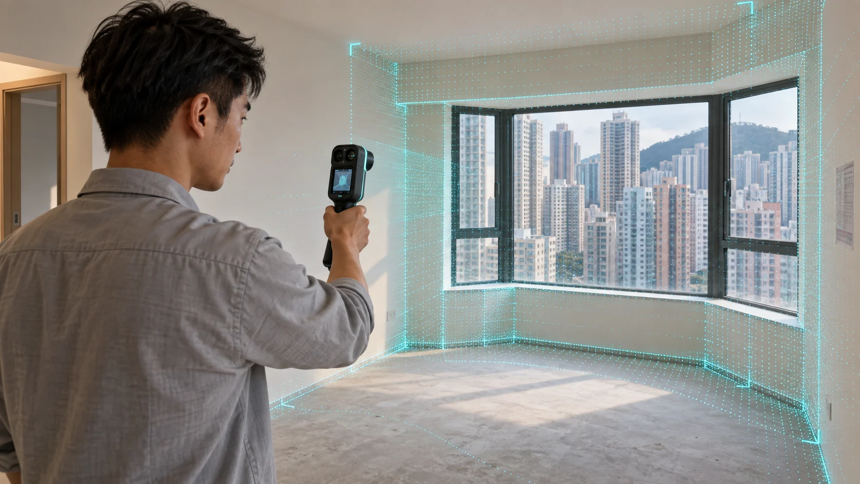
Capture equipment: 3DGS on-site scanning primarily uses handheld scanners — a typical example is the XGRIDS PortalCam, a compact device with a front-mounted lens array. The operator walks the space along a planned route, systematically covering the entire environment. This mobile approach is considerably more flexible than fixed-tripod LiDAR scanning in geometrically complex interiors such as spiral staircases, M&E service shafts, and narrow corridors.
The key workflow difference between 3DGS and other technologies lies in Stage 3: “scene training” is a step unique to 3DGS, and it is precisely why the visual quality of 3DGS output far exceeds traditional mesh reconstruction. This step requires relatively high computational resources, but the result is a space you can “walk into” smoothly in a standard web browser — no specialist 3D software or high-end workstation required.
Selection Criteria: Choosing Your Technology by Project Characteristics
Rather than asking “which technology is best,” ask “what does my project most need?” Here is a decision framework:
| Project Characteristic | Recommended Primary Technology | Alternative |
|---|---|---|
| High geometric complexity (spiral staircases, M&E pipework, irregular spaces) | 3DGS | LiDAR (when engineering precision is the priority) |
| Visual fidelity as the primary output (showcasing, tours, training, heritage conservation) | 3DGS | Matterport (standard rectangular indoor spaces) |
| Area measurement, floor plan generation, handover documentation | Matterport | LiDAR |
| Outdoor building facade documentation, cultural heritage archiving | Photogrammetry | LiDAR |
| Engineering measurement precision, BIM integration, M&E routing verification | LiDAR | Photogrammetry |
| Requires a “walkthrough” experience in VR or browser | 3DGS | Matterport (constrained by platform ecosystem) |
| Phase-by-phase documentation of a fast-changing construction site | Photogrammetry (rapid on-site capture) | LiDAR |
| Poor lighting conditions (windowless plant rooms, night-time, dark spaces) | LiDAR | 3DGS (viable with supplemental lighting) |
Real Hong Kong Scenarios: Three Typical Examples
The following are descriptive examples of common scanning needs in Hong Kong. No specific projects or clients are named.
Tong lau staircase heritage documentation: An owner or NGO needs a complete visual record of a pre-war tenement building before demolition or renovation — the carved detail on cast-iron banisters, the plaster texture on ceilings, the angle of natural light falling through a rooftop skylight. The visual detail density required in this type of scene is precisely where 3DGS holds its clearest advantage over alternative technologies. Photogrammetry can achieve similar results, but 3DGS output lets the viewer “walk through” the space rather than simply browse a static model.
Industrial building floor-plate assessment: An owner needs accurate floor area, column positions, and corridor widths, and also wants prospective tenants to get a feel for the space. Matterport’s measurement tools are directly applicable here: the floor plans and area figures it generates are accurate and suitable for commercial use.
Building plant room M&E routing verification: An M&E engineer needs to verify whether existing pipework in a plant room matches the construction drawings, and to identify unrecorded services occupying space. LiDAR point cloud geometric precision is a baseline requirement for this scenario — visual quality is a secondary consideration. Engineers are reading data, not images.
3DGS as the Base Environment for VR Training
Beyond static documentation and showcasing, one increasingly common application for 3DGS is as the base scene layer for VR training.
Traditional VR training environments are modelled from scratch by designers — flexible, but the resulting scenes feel disconnected from the employee’s actual workplace. When you scan a real working environment into a 3DGS scene and layer in interactive training elements — marking hazard points, setting decision triggers, simulating the consequences of incidents — trainees learn inside a space they recognise. Spatial memory and training memory connect directly, improving transfer of learning.
This approach is particularly well-suited to complex working environments such as M&E plant rooms, exhibition venues, and property management operations centres — spaces where the geometric complexity and detail would take considerable time to recreate through traditional modelling, but which 3DGS can capture on-site directly.
To learn about VTM’s 3DGS service scope and delivery approach, visit the VTM 3DGS Service Page.
Technical Background: Where Did 3DGS Come From?
The academic foundation of 3DGS technology is the paper 《3D Gaussian Splatting for Real-Time Radiance Field Rendering》 by Kerbl et al., published at SIGGRAPH 2023. The paper proposed replacing traditional Neural Radiance Fields (NeRF) with Gaussian primitives — maintaining high visual fidelity while dramatically increasing real-time rendering speed. This is the technical reason 3DGS can render smoothly in a standard web browser. The full paper is freely available; readers interested in the technical detail can consult the original research directly.
Frequently Asked Questions
Work Backwards from Your Requirements — Then Choose the Right Tool
The core question in any scanning project is not “which technology is newer or better,” but “what am I ultimately going to do with this 3D scene?” Presenting to a client, embedding in VR training, or verifying engineering precision — these three purposes map to three very different optimal technologies.
If your project involves visual reconstruction of a geometrically complex space, or bringing a real environment into a VR training programme, 3DGS is the direction worth evaluating first. Find out more at the VTM 3DGS Service Page.
Learn about VTM’s 3DGS reality-capture service and get a solution recommendation tailored to your project
VTM 3DGS Service DetailsReferences
- Kerbl et al. (2023): 3D Gaussian Splatting for Real-Time Radiance Field Rendering — SIGGRAPH 2023: repo-sam.inria.fr/fungraph/3d-gaussian-splatting
Technology comparisons in this article are general descriptions. Platform capabilities and output formats are subject to change with version updates; we recommend verifying the latest specifications directly with each technology provider.
Further Reading